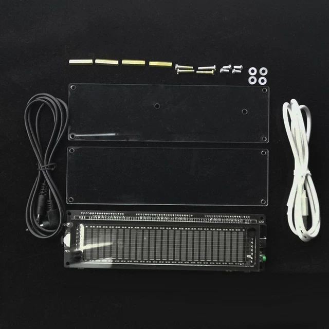
DIY KIT LED Audio Spectrum Audio Spectrum Analyzer 33 Green Modules Circuit Diagram
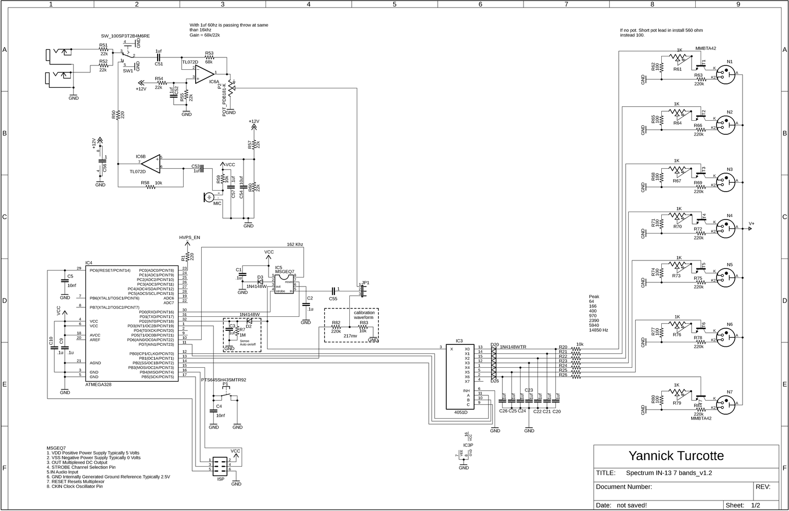
DIY KIT LED Audio Spectrum Audio Spectrum Analyzer 33 Green Modules Circuit Diagram Step 4: LED Audio Spectrum Analyzer Circuit and PCB Here we use EasyEDA to design the control panel. EasyEDA is a simple and efficient online EDA designing software, by which you can draw a diagram or cut a pattern conveniently.
If we add an AGC/ALC circuit with the Audio Spectrum Analyzer circuit, the LED display can work irrespective of amplifiers volume control setting. Eg:- If I take audio input from speaker terminals (such cases when a preamplifier output is not accessable), the displays beauty will lose when we increase and decrease amplifiers volume.

Creating Your Very Own DIY Spectrum Analyzer in 9 Easy Steps Circuit Diagram
[Ryan] wanted a spectrum analyzer for his audio equipment. Rather than grab a micro, he did it the analog way. [Ryan] designed a 10 band audio spectrum analyzer. This means that he needs 10 band The first step of this circuit is to build a 200dB stereo amplifier. (It does not have to be stereo but it is recommended. This does not replace an audio mixer.) This also does not need to be soldered. I only did so because I would use this over and over again. So if you do plan to use it often, it is a good idea to make it permanent.

Run an audio signal through it and you have an instant audio spectrum analyzer! This is a simple spectrum analyzer based on an Arduino. Each of the 5 LEDs represent a single section of the chip's 7 sections of audio spectrum. Hi, I am trying to build this circuit. I have checked my wiring and connections and for some reason the lights don
Build An Audio Spectrum Analyzer The Analog Way Circuit Diagram
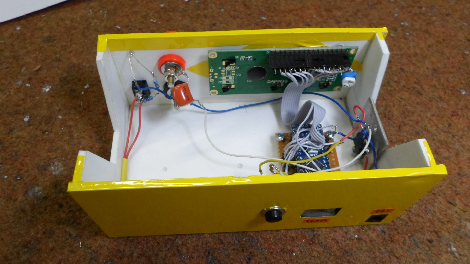
A spectrum analyzer measures the magnitude of an input signal versus frequency within the full frequency range of the instrument. In this project is presented a very simple way in which such a device can be made with the help of only a few components: - Arduino Nano microcontroller - 16X2 LCD display - capacitor 47 nF and